In this post, you’ll learn what is a centrifugal pump and how it works? Its diagram, parts, types, and difference between centrifugal pump and reciprocating pump.
Also, you can download the PDF file of this article at the end.
What is Centrifugal Pump?
It is one of the simple and exciting topics in fluid mechanics. What is the need for a pump? We require a pump to transmit water from a region of low pressure to a region of higher pressure.
The centrifugal pump defines as a hydraulic machine that converts mechanical energy into hydraulic energy by means of a centrifugal force acting on the fluid.
In this, the pump uses a centrifugal force acting on the fluid surface to convert the mechanical energy. The centrifugal pump flows in a radially outward direction. Therefore the pump acts like a reverse reaction turbine. These pumps are used to raise the water or liquid from a lower level to a higher level.
The first centrifugal pump is invented in the 17 century. After that, Denis Papin modified the centrifugal pump with straight blades. Again in 1851, British discoverer John Appold invented a curved vane centrifugal pump.
Nowadays, centrifugal pumps are commonly used in worldwide industrial applications. They are extensively used because the pump has no power loss due to friction. It has a simple design and is very easy to control. In addition, they do not have problems with leakage and heat transfer.
Read Also: Types of Pumps and Their Working [Explained]
Parts of Centrifugal Pump
The different parts of the centrifugal pump are listed below.
- Shaft and shaft sleeve
- Impeller
- Casing
- Suction Pipe
- Delivery Pipe
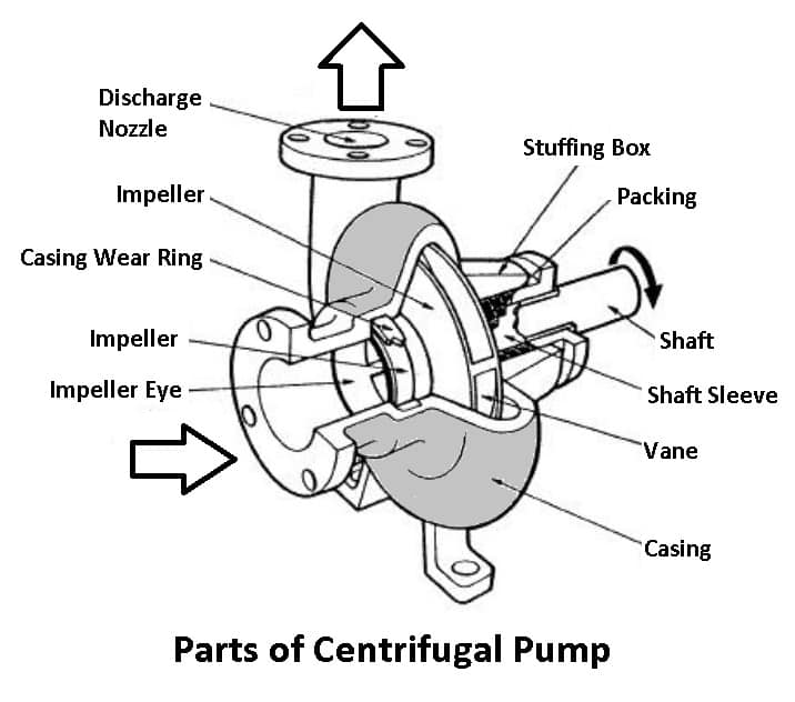
#1 Shaft and shaft sleeve
The shaft is a central part of the pump, which rotates with the connected impeller. It is coupled with the prime mover to get the power. The shaft fits with the ball bearing.
A shaft sleeve is also employed, which prevents the shaft of the pump from leakage and corrosion. One end of the sleeve should be sealed.
#2 Impeller
The impeller consists of a series of backward-curved vanes. It is mounted to the shaft of an electric motor. An impeller is a rotating part of the centrifugal pump. It is enclosed in a watertight casing. The centrifugal pump impeller is divided into three types.
a) Open Impeller
An open impeller consists of vanes attached to a central hub and mounted directly on the shaft. The vanes have no walls or cover around them, making open impellers weaker than closed valves. Still, these are generally quick and easy to clean and repair.
b) Closed Impeller
The closed impeller has both front and back cover plates. In this, the impeller vanes are sandwiched between two cover plates. These are installed in radial flow centrifugal pumps and can be either single or double inlets. Also, it uses to obtain pure water.
c) Semi-open impeller
Semi-open impellers have a back-wall cover plate that gives mechanical power to the van, while the other side remains open. Semi-open impellers are used in medium-sized pumps. This impeller is designed for debris-loading fluid.
#3 Casing
The casing is an airtight passage surrounding the impeller. It is designed in such a way that the kinetic energy of the water discharged at the outlet is converted into pressure energy before the water leaves the casing and enters the delivery pipe.
The casing works as a cover to protect the system. The casing of the centrifugal pump is further classified into three types.
a) Volute casing (Spiral casing)
It is surrounded by the impeller. Such a casing provides a gradual increase in the area of a flow, thus decreasing the velocity of water and correspondingly increasing the pressure.
b) Vortex casing
A vortex casing is a circular chamber introduced between the impeller and casing. here the fluid from the impeller has to first pass through the vortex chamber and then through the volute casing. In such a case, there is a better conversion done that is velocity energy into pressure, and it has good efficiency than the volute casing.
c) Casing with Guide Blades
In a casing with guide blades, the blades surround the impeller. These blades are designed and arranged in such a way that the water from the impeller enters the guide vane without shock and creates a passage of increasing area, through which the water passes and reaches the delivery to leave with pressure.
#4 Suction Pipe with a Foot Valve and Strainer
The suction pipe has two ends. One end is connected to the inlet of the pump and the other dips into the water in a sump.
A foot valve fits at the lower end of the suction pipe. The foot valve is a one-way type of valve that only opens in an upward direction. A strainer is also fitted at the end of the suction pipe to prevent the entry of foreign bodies into the suction pipe.
#5 Delivery valve
The delivery valve also has two ends. One end is connected to the outlet of the pump, and the other end delivers the water at the required height.
Read also: What is Impulse Turbine and Pelton Wheel [Parts & Working]
Working Principle of Centrifugal Pump
Priming is the initial phase of a centrifugal pump’s operation. The process of priming involves filling the pump’s suction pipe casing with the liquid to be pumped and positioning the fluid so that all air is driven out of the pump’s position and no air is left.
The need for priming a centrifugal pump is caused by the fact that the pressure produced at the impeller is inversely proportional to the density of the fluid in contact with it.
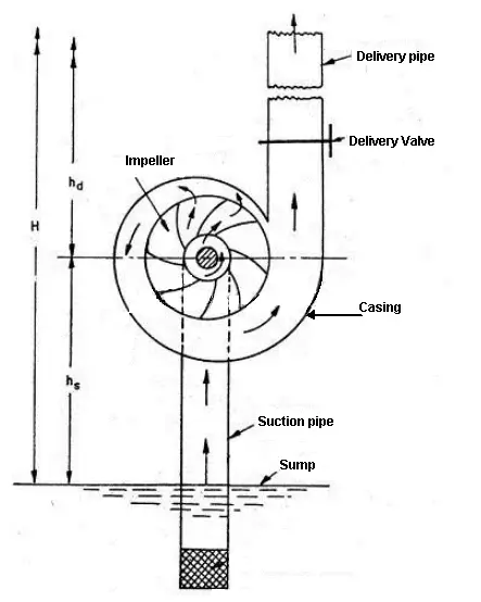
The delivery valve is kept closed after the pump has been primed while the electric motor is turned on to rotate the impeller. When the delivery valve is opened, the liquid flows outward in a radial direction by impeller vanes at the outer circumference with high velocity, creating a vacuum. The delivery valve is kept closed to minimize this effect.
This causes the sump’s liquid to move quickly through the suction pipe to the impeller’s eye, replacing the long discharge from the impeller’s center circumference, which is used to lift the liquid to the necessary height through the delivery pipe.
Priming In A Centrifugal Pump
Priming is the operation in which the suction pipe, casing of the pump, and a portion of the pipe up to the delivery valve are filled up from an outside source with the liquid to be raised by the pump before starting the pump.
Read Also: What is the function of Flow Control Valves? Types & Uses [PDF]
Types of Centrifugal Pumps
Different types of centrifugal pumps are widely used in various industries worldwide. These pumps are classified based on the number of impellers, type of casing, orientation, and position.
- Based on the number of impellers
- Single stage impeller
- Multistage impeller
- Based on the type of casing
- Turbine pump
- Volute pump
- Based on the orientation of the fluid
- Radial flow pump
- Axial flow pump
- Mixed flow pump
- Based on the position of the pump
- Horizontal pump
- Vertical pump
- Submersible pump
#1 Single-Stage Centrifugal Pump
It consists only of an impeller that rotates on a shaft within a pump casing. It is designed to produce fluid flow by using a motor. Single-stage centrifugal pump is one of the simplest types of pumps available in many variations in design.
#2 Multistage Centrifugal Pump
The multistage centrifugal pump consists of more than one impeller connected in series in the pump casing. In this, the fluid enters from the first impeller under the pressure of the suction line and leaves at some high pressure.
While leaving the first stage, the fluid enters the second stage, where the pressure increases further. These pumps provide better efficiency due to tighter impeller clearance and smaller impeller diameters.
#3 Turbine Pump
Turbine pumps are the most popular type of centrifugal pump. It consists of the number of blades mounted on the impeller. These blades are fixed to the diffuser ring. The space between the blades defines the direction of the liquid flow.
Fluid from the impeller flows through the cavities under high pressure. Upon exiting the blade, the liquid enters the housing of a volute or spherical shape. They are used in clean liquid applications that require high head, low flow, compact design, and flexible operation.
#4 Volute Pump
In this type, the impeller of the pump is covered in the volute casing. It receives the fluid being pumped by the impeller, maintaining the velocity of the fluid through the diffuser. When the liquid exits the impeller, it has high kinetic energy, and the volute controls this flow to discharge.
It is designed in such a way that fluids with equal speed can exit the impeller and enter the pump. The volute pump provides minimal energy losses. These pumps cannot convert kinetic energy into maximum-valued potential energy.
#5 Radial Flow Pump
It is a type of centrifugal pump in which the controlled fluid leaves the impeller in a radial direction. The radial movement of flow in the impeller causes high centrifugal force. This converts to higher discharge pressures but usually lower volume flow rates.
These pumps are commonly used for lift irrigation and drainage of agricultural land. In addition, they are also used in nuclear power plants, seawater handling, freshwater supply, boiler feed, or other applications.
Read Also: 12 Types of Heat Exchangers & Their Application
#6 Axial Flow Pump
In this type, water enters the pump radially while discharging axially. Therefore, these pumps are called axial flow pumps. An axial flow pump provides a relatively high discharge (flow rate) at a relatively short head (vertical distance).
These pumps are generally employed for large volume flows over small delivery heads. Axial pumps are used to propel incompressible fluids.
#7 Mixed Flow Pump
As the name suggests, it is a moderate direction between radial (perpendicular to the axis) and axial (along the axis). In this, the fluid moves along the axis of the impeller for half the distance. After that, it starts moving perpendicular to the axis (radially).
#8 Horizontal Pump
The operation of this pump is based on the fluid being continuously pumped from a suction nozzle located at the center of the impeller. A horizontal pump delivers liquid at a very high speed by using a drive motor.
It ensures efficient fluid flow. Since the pump offers excellent performance, it is sealed very tightly, and these are eco-friendly pumps. These pumps are reliable enough for a wide variety of water applications.
#9 Vertical Pump
These pumps also deliver liquids using a motor. It has a high water flow rate and is suitable for high-speed transport of chemicals. The vertical pump uses a bearing support device to drop the vortex into the water tank.
These bearings are mounted on the outside of the water tank, and it also uses a shaft for rotation. It is designed to handle corrosive liquids in wastewater treatment, sump drainage, tank transfer, and other industrial applications.
#10 Submersible Pump
This pump moves the water to the surface by converting rotary energy into kinetic energy into pressure energy. This is done by drawing water into the pump. In the intake, the rotation of the impeller pushes the water through the diffuser. From the diffuser, it is delivered to the surface.
These pumps supply gray water, black waste, underground soil, good water, rainwater, chemicals, and other moisture. These pumps are selected according to the fluid high head and low flow or low head and high flow rate.
Read Also: Different Types of Pneumatic Valves & Their Applications [PDF]
Necessary For a Centrifugal Pump
The pressure developed by the impeller of a centrifugal pump is proportional to the density of the fluid in the impeller. If the impeller is running in the air, it will produce negligible pressure, which may not suck water through the suction pipe. To avoid this, the pump is first primed, i.e., filled with water.
Read also: What is Reciprocating Pumps? Working Principles of Reciprocating Pump
Difference Between Centrifugal Pump and Reciprocating Pump
The following are the main difference between centrifugal and reciprocating pumps:
| Centrifugal Pump | Reciprocating Pump |
|---|---|
| Centrifugal pump is imple in construction due to less number of parts. | Reciprocating pump is complicated in construction due to more number of parts. |
| Centrifugal pump has more weight due to a given discharge. | While the reciprocating pump has less weight of pump for a given discharge. |
| Centrifugal pumps are suitable for large discharge with a small head. | Whereas reciprocating pumps are suitable for less discharge with a high head. |
| Centrifugal pump requires more floor space and heavy foundation. | The reciprocating pump requires less floor space with a simple foundation. |
| Centrifugal pump has less wear and tear and can handle dirty water. | The reciprocating pump has more wear and tear and cannot handle dirty water. |
| Centrifugal pump delivery is continuous and needs priming. | Whereas reciprocating pump delivery is pulsating and does not need priming. |
| Centrifugal pump has low efficiency and can run higher. | Whereas the reciprocating pump has high efficiency and cannot run at a higher speed. |
| Centrifugal pump has less maintenance cost. | Reciprocating pump has more maintenance cost. |
| It cannot require air vessels, and operation is quite. | It requires air vessels, and operation is complicated. |
| In this, the thrust on the crankshaft is uniform. | In this, thrust on the crankshaft is not uniform. |
Read Also: Different Types of Manometers and Their Applications
Advantages of Centrifugal Pump
- The most significant advantage of centrifugal pumps is their simplicity.
- They are suitable for large discharge and smaller heads.
- They don’t require any valves or many moving parts.
- This pump allows them to run at high speeds with minimal maintenance.
- Their output is very steady and consistent.
- Centrifugal pumps provide a lot of flexibility, are easy to move, and don’t take up a lot of space.
Disadvantages of Centrifugal Pump
- The pump uses rotation rather than suction to move the water. Therefore, it has no suction power.
- Centrifugal pumps always face cavitation problems.
- During pump operation, there may be a possibility of misalignment of the shaft.
- These pumps are not built to operate with highly viscous liquids as well as high heads.
- It also damages the seal ring, worn ring, and impeller.
Application of Centrifugal Pump
- These pumps are popularly used in domestic applications like pumping water from one place to another.
- They are also used in refrigerant and coolant recirculation.
- This pump is also used for drainage, irrigation, and sprinkling.
- Centrifugal pumps are widely used in gas and oil industries for pumping slurry, mud, and oil.
- These pumps are also valuable for sewage systems.
- These are employed by the industrial and fire protection sectors, including sprinkler systems for fire protection, heating and ventilation, boiler feed applications, air conditioning, and pressure boosting.
That’s it. Thanks for reading. If you have any questions or doubts, leave a comment. If you found this article helpful, please share it with your friends.
Want free PDFs in your inbox? Then subscribe to our newsletter.
Download PDF of this article:
Read more on this blog:
- Shaper machine and types of shaper machine.
- Why drilling machines are used?
- Types Of CNC Machines and Their Working [Complete Guide]
- Different Types of Grinding Machines [Complete Guide]
- Difference Between Up Milling and Down Milling
- 13 Main Differences between NC, CNC, and DNC Machine
- What are Different Shaper Machine Operations?
- Different Types of Shaper Machine Mechanism
- Types of Lathe Cutting Tools Used in Lathe Machine
- How Does A Planer Machine Work?
External Links:
- https://en.wikipedia.org/wiki/Centrifugal_pump
- https://www.gcoeara.ac.in/Unit_IV_Centrifugal_Pump.pdf
Frequently Asked Questions
The centrifugal pump is a mechanical device that moves fluid by transferring rotational energy from one or more driven rotors, known as impellers. Centrifugal force causes fluid to be thrown out of the rapidly rotating impeller along its circumference through the vane tips.
Many sectors around the world use various types of centrifugal pumps. These pumps are classified according to the number of impellers, casing type, orientation, and position.
1. Based on the number of impellers
b) Single stage impeller
a) Multistage impeller
2. Based on the type of casing
a) Turbine pump
b) Volute pump
3. Based on the orientation of the fluid
a) Radial flow pump
b) Axial flow pump
c) Mixed flow pump
4. Based on the position of the pump
a) Horizontal pump
b) Vertical pump
c) Submersible pump
The following details enable us to choose an essential centrifugal pump;
1. Liquid name
2. Flow rate
3. Pressure
4. Viscosity
5. Density
6. Temperature
Positive displacement pumps force fluid out of the cavity through suction after drawing the fluid into the cavity or displacing the fluid. The fluid is drawn into centrifugal or aerodynamic pumps by a rotating impeller, which also accelerates the fluid’s exit from the pump’s outlet point.
Because centrifugal pumps can be damaged by solids, they are commonly associated with handling clean fluids. However, if the proper impeller is chosen, they can occasionally be used as reliable transfer pumps.
Thanks for sharing the blog on Centrifugal Pump. It is a very informative post.
You’re welcome.
This Pump Service is good
Thanks for reading.
I found it hard downloading this pump article.pls help me out
I have updated the article with the new PDF file, now you can download it.
Content is very meaningful and clearly. Thankyou so much =))
You’re welcome 🙂
Tq u so much
You’re welcome 🙂
Thank very much
You’re welcome